ON THIS PAGE
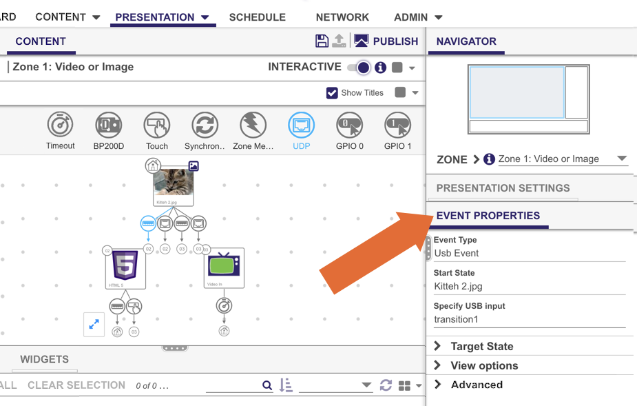
The Event Properties pane allows you to view and edit settings associated with interactive events. To view the Event Properties of an event, select an event that is part of your interactive playlist in the Content tab. Each event will have different properties associated with it. The Event Properties pane for all events will also contain Target State, View Options, and Advanced menus:
- Target State lets users change the state of the event (to transition to a new state, return to a prior state, or remain on the current state.
- View Options lets users change how the event is viewed in the content window by showing labels or lines, and positioning labels.
- Advanced allows users to add entry and exit commands to that state.
Common Event Properties
All event types have the following properties. For event-specific properties, see the event descriptions below.
- Event Type: The event type (e.g. Timeout, Zone Message)
- Start State: The state that the event is transitioning from
Target State
Specify what should occur when the event is triggered:
- Transition to new state: The playlist will transition to a new state when the event is triggered. Use the dropdown list to specify the transition target.
- Return to prior state: The playlist will revert to the previous state when the event is triggered.
- Remain on current state: The state will not change when the event is triggered. This option is useful when you need to perform actions that are not immediately visible, such as sending a UDP command, altering the value of a user variable, or lowering the volume. These actions are performed by attaching commands to an event.
- Continuous: Audio/video playback is unaffected when the event is triggered.
- Stop playback: Audio/video playback stops when the event is triggered, and the stopped frame is displayed for video files.
- Stop playback and clear screen: Audio/video playback stops when the event is triggered, and the playback area is cleared.
View Options
Customize how the event is displayed in the playlist UI.
- Show line: Displays a line between the two states connected by the event.
- Show label: Displays numbered event labels on the two states connected by the event.
Advanced
See the Conditional Targets and Commands page to learn more about the options in the Advanced section.
Timeout Event
The Timeout event displays a state for a predetermined period of time before the event is triggered.
In the Time on screen field, specify the number of seconds the state should display before the trigger. A zero value will display the state indefinitely.
Media End Event
The Media End event is triggered when a video or audio file reaches the end of playback.
Media List End Event
The Media List End event is triggered when the last item in a Media List reaches the end of playback. All other items in a Media List trigger the Media End event.
Note
The Media List End event can only originate from a Media List state.
BP900/BP200 Event
The BP900 and BP200 events trigger when a BP900 or BP200 button is pressed. The BP900 and BP200 button panels are LED-based touch devices that allow you to add button interactivity to BrightSign players with a USB port.
Enumeration
There are a total of eight event icons: BP900A, BP900B, BP900C, BP900D, along with BP200A, BP200B, BP200C, and BP200D. The letters A, B, C, and D correspond to USB ports. If the event you are defining is for a button pad connected to USB port A, use "A". If it is for a button pad connected to the second port, use B.
Example
An XD1134 has two available USB ports. If you want to connect two button boards, a BP900 to port A and a BP200 to port B, you would use the BP900A and BP200B icons to define events for each.
You can use a USB hub to connect up to four BP900/BP200 button panels to a BrightSign player. See this tech note to learn more about BP900/BP200 enumeration on USB hubs.
Event Properties
- Specify Button Number: Select a button on the button pad that you want the user to press to transition to the next state.
Important
Selecting Any Button will enable only the button numbers used in other BP200 or BP900 events in the presentation (or numbers enabled in the Presentation Settings > Interactive > Touch section): For example, if you have defined BP900 events for buttons 1 and 4, a BP900 event set to Any Button will trigger for buttons 1 and 4 only.
- Press (First Touch): The event triggers once at the moment the button is pressed.
- Press Continuous: The event triggers the moment the button is depressed, then continues triggering at the specified Repeat interval in milliseconds as long as the button is depressed.
Touch Event
The Touch event triggers when the user presses a region on a touch screen that is connected to the BrightSign player. Click the Set Touch Regions button in the Event Properties pane to define touch regions that will trigger the event.
Click ![]() Add Touch Region to add a new Touch event to the state: Each Touch event corresponds to a single touch region. Select a touch region to edit the transition as well as the exact positioning of the region:
Add Touch Region to add a new Touch event to the state: Each Touch event corresponds to a single touch region. Select a touch region to edit the transition as well as the exact positioning of the region:
- Size: Set an exact size for the touch region. Alternatively, you can click and drag the marks surrounding the touch rectangle to change its size.
- W: Enter the pixel width of the touch region.
- H: Enter the pixel height of the touch region.
- Position: Set an exact position for the touch region. Alternatively, you can click and drag the rectangle to a different area.
- X: Enter the horizontal position (in pixels) of the top-left corner of the touch region.
- Y: Enter the vertical position (in pixels) of the top-left corner of the touch region.
- Advanced Commands: Add commands or conditional targets.
Once you are finished editing the touch region, click the Zone description located in the top left corner of the canvas. This will take you back to the Zone Content canvas.
Synchronize Event
The Synchronize event synchronizes playback with other BrightSign players on the same local network using UDP. This event is useful for synchronizing playback according to user input.
This event triggers when a Synchronize command with the same keyword as the Synchronize event is used on another player on the local network. Enter the keyword that corresponds to the Synchronize command in the Specify synchronization keyword field.
For Synchronize events to work, you must ensure UDP communication is configured correctly in Presentation Settings > Interactive > Networking.
Zone Message Event
The Zone Message event allows you synchronize content between zones. This event is compatible with all state types, while the Link Zones event only works with video and image states; however, the Link Zones event provides better synchronization times because it pre-loads the next image/video file before displaying it.
Zone Message events can be used with Synchronize events to synchronize zones in a multi-screen presentation, while Link Zones events cannot be used with Synchronization events.
In the Specify zone message field, enter the message that is sent by the corresponding Send Zone Message command.
UDP Event
The UDP Input event triggers when the BrightSign player receives a UDP (User Datagram Protocol) message from another device on the local network. Source devices can include tablets/smartphones running the BrightSign App, other BrightSign players, and PCs/Macs.
- Specify UDP input: Enter the UDP message string that will trigger the event. You can also use the <any> wildcard to match some or all of the UDP message string (i.e. entering "<any>" in this field will match all UDP messages, while entering "mycommand_<any>" will match any UDP message that begins with "mycommand_").
- Label: Specify a label for the UDP command button in the BrightSign App. By default, the command label will be the same as the UDP message string.
- Show in BrightSign App: Display the command button corresponding to the UDP Input in the BrightSign App.
- Assign input to variable: Assign the content of the UDP message to a User Variable.
- Input specifies variable: The UDP message string will dynamically specify which User Variable to modify. The UDP message string must be sent in the form of "<variable name> : <variable value>".
- Specify fixed variable: The UDP string will modify a fixed User Variable. Use the dropdown list to choose which User Variable the UDP input will modify. The UDP string must be sent in the form of "<variable value>".
Tip
You can use the Input specifies variable option to modify more than one User Variable with a single event. Use the following UDP string format: "<variable name> : <variable value> !! <variable name> : <variable value>"
- Assign wildcard to variable: Specify the value of a User Variable using the <any> wildcard. Select the User Variable to modify using the dropdown menu to the right. The Specify UDP Input field must contain the <any> wildcard, either by itself or with additional text (e.g. "message_<any>").
GPIO Event
The GPIO event triggers when a specific GPIO button is pressed or input is received. The playlist toolbar includes the different GPIO button numbers that you can use to define interactions.
- Specify button number: Specify the number of the GPIO button.
- Trigger Event on Button: Specify whether the event should trigger when the button is depressed (Down) or when it is released (Up). If you've selected Down, choose one of the following behaviors:
- Press (First Touch): The event triggers once at the moment the button is depressed.
- Press Continuous: The event triggers the moment the button is depressed, then continues triggering at the specified Repeat interval in milliseconds as long as the button is depressed.
Note
The "button" numbers described above are not the same as GPIO "pin" numbers: Some pins act as power supply or ground, so they are not included in the button numbering scheme. See the Hardware Interfaces section of the hardware manual associated with your player model to view a mapping of buttons to pins.
Plugin Message Event
The Plugin Message event triggers when a message is received from a custom script plugin that is attached to the presentation. See the Parsers and Plugins tech note for more information on creating custom scripts that send plugin messages.
- Plugin Name: Use the dropdown menu to determine which plugin the event can receive messages from.
- Specify Plugin Message input: Enter the message string that will trigger the event. You can also use the <*> wildcard to match some or all of the plugin message string (i.e. entering "<*>" in this field will match all plugin messages, while entering "mycommand_<*>" will match any plugin message that begins with "mycommand_").
- Assign input to variable: Assign the content of the Plugin Message to a User Variable.
- Input specifies variable: The Plugin Message string will dynamically specify which User Variable to modify. The Plugin Message string must be sent in the form of "<variable name> : <variable value>.
- Specify fixed variable: The Plugin Message string will modify a fixed User Variable. Use the dropdown list to choose the User Variable to modify. The Plugin Message string must be sent in the form of <variable value>".
Tip
You can use the Input specifies variable option to modify more than one User Variable with a single event. Use the following Plugin Message string format: "<variable name> : <variable value> !! <variable name> : <variable value>".
- Assign wildcard to variable: Specify the value of a User Variable using the <any> wildcard. Select the User Variable to modify using the dropdown menu to the right. The Specify Plugin Message input field must contain the <any> wildcard, either by itself or with additional text (e.g. "message_<any>").
USB Event
The USB event triggers when a BrightSign player receives the specified input from a connected USB device.
In the Specify USB input field, enter the USB input string that will trigger the event.
Keyboard Event
The Keyboard event triggers when a BrightSign player receives the specified input from a connected keyboard.
In the Specify keyboard input field, enter the keyboard input that will trigger the event.
Remote Input Event
The Remote Input event triggers when the BrightSign player receives the specified input from an IR remote control.
In the Specify remote input field, enter the NEC remote control code that will trigger the event.
Video Time Code / Audio Time Code Event
The Video Time Code and Audio Time Code events perform commands at specific times during video or audio file playback. If you want to trigger a transition at a certain point in a video or audio file, use the Timeout event instead.
Click the ![]() Add Time Code button to add a new time-code command. Enter the Timeout interval for the command (in milliseconds), and then select the Command and Parameters from the corresponding lists.
Add Time Code button to add a new time-code command. Enter the Timeout interval for the command (in milliseconds), and then select the Command and Parameters from the corresponding lists.
Time/Clock Event
The Time/Clock event triggers at a specific time and date or at regular intervals on a recurring schedule.
- Single date/time event: Specify a one-time-only event.
- Date: Specify the time and date of the event.
- Specify with user variable: Use the value of a User Variable to specify the date and time. Choose a variable from the dropdown list. The value of the variable must be in this format: “yyyy-mm-ddThh:mm:ss”. For example, if you would like the event to occur on December 20, 2021 at 3:45PM, then you would use the value “2021-12-20T15:45:00”.
- Daily timeout event: Specify a recurring event.
- Once per day: Select this option to have the event occur once per day at the specified Time.
- Periodic throughout the day: Select this option to have the event occur at intervals throughout the day.
- Interval between events: Determine the frequency of the recurring event (in minutes).
- Active between: Specify the period during which recurring events can trigger.
- Set the days the timeout is active: Select which days the time/clock event is active.
Link Zones Event
Use the Link Zones event, combined with the Link Zones command, when you require close, millisecond-level synchronization of content between zones on the same player.
The Link Zones event supports video and image states only; use the Zone Message event to synchronize other states. The Link Zones event provides better synchronization times than the Zone Message event because it pre-loads the next image/video file before displaying it.
Link Zones events cannot be used in the same presentation as Synchronize events; to synchronize zones in a multi-screen presentation, use the Zone Message event.
In the Specify link keyword field, enter the message that is sent by the corresponding Link Zones command.
Serial Input Event
The Serial Input event triggers when the BrightSign player receives input from a device connected to a serial port.
- Specify port: Enter the port number of the input device. Most standard RS-232 serial devices enumerate on port 0. If you are connecting a USB-serial device, it will enumerate on port 2. To configure the serial port, navigate to Presentation Settings > Interactive > Connectors.
- Specify serial input: Enter the serial input string that will trigger the event. You can also use the <*> wildcard to match some or all of the serial input (i.e. entering "<*>" in this field will match any input, while entering "mycommand_<*>" will match any input message that begins with "mycommand_").
- Assign input to variable?: Check this box to assign the content of the serial input to a User Variable.
- Input specifies variable: The serial input string will dynamically specify which User Variable to modify. The serial input string must be sent in the form of "<variable name> : <variable value>".
- Specify fixed variable: The serial input string will modify a fixed User Variable. Use the dropdown list to choose which User Variable the serial input will modify. The serial input string must be sent in the form of "<variable value>".
Tip
You can use the Input specifies variable option to modify more than one User Variable with a single event. Use the following serial input string: "<variable name> : <variable value> !! <variable name> : <variable value>".
- Assign wildcard to variable?: Check this box to specify the value of a User Variable using the <*> wildcard. Select the User Variable to modify using the dropdown menu to the right. The Specify serial input field must contain the <*> wildcard, either by itself or with additional text (e.g. "message_<*>").
Note
Wildcards are only supported when the serial port is using the ASCII protocol, not when using the Binary protocol.